
Case study: Electrical system design for hospital campuses
Learning Objectives
- Learn about master planning design and expectations with owners.
- Understand design considerations for electrical infrastructure in a campus expansion.
- Look at electrical room layout considerations.
Insights:
- When figuring the blocking and stacking analysis, it is important for the engineering team to coordinate with the architect on space requirements for the electrical room and placement of infrastructure routing.
- Drawbacks to using custom sized equipment in this situation were first cost and lead time implications, life cycle maintenance cost and complexity.
- An important part in the design of large-scale generator plants, especially in urban areas, are the acoustic and pollution control considerations. In this case, the team enhanced pollution control and sound attenuation was included in the central plant design.
A major pediatric health care provider in Atlanta is expanding its campus and will greatly increase the number of patient beds to its existing portfolio. WSP USA is the primary mechanical, electrical and plumbing engineering firm for this 1.44-million-square-foot expansion that began master planning in 2017 and is set to open to the public in 2024.
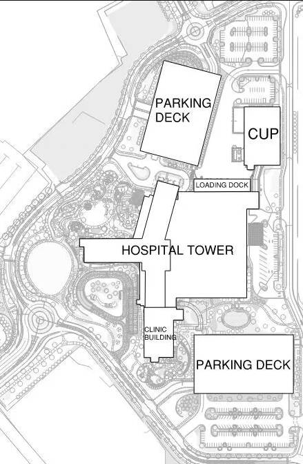
This expansion includes a new central plant (50,000 square feet), standalone hospital (1.3 million square feet), clinic building (500,000 square feet) and parking garages. During the pre-design and master planning phase, the engineering team needed to consider various campus infrastructure and expansion scenarios.
Master Planning and utility coordination
Before designing the room layouts of the buildings, major site and electrical utility capacity coordination and planning needed to occur. The owner provided parameters for the buildings and the desired bed count for the initial build and various expansion scenarios. These gave the design team a starting point to begin spatially locating various buildings and infrastructure within the site to optimize the layout of the new campus.
During master planning the key question to answer is, ‘What are we currently designing to, and what future capacity do we need to plan for in our design?’
The answer is key as it will drive the entire design and affect the initial central plant capacity and ability for expansion to serve the current campus plan, as well as any future expansions. The electrical system capacity was going to include serving the initial buildings, as well as planned shell floors withing the initial build and future tower expansions and additions to the hospital and clinic building.
At this stage, the architectural design partners on the design team started working toward various blocking and stacking diagrams that helped inform engineering and infrastructure calculations. This stage of design is crucial for the engineering team to coordinate with the architect on space requirements for equipment rooms and placement of infrastructure routing. To provide this information to the architectural design partner, the engineering team had to first determine how to best distribute electrical, mechanical and plumbing throughout the building to meet the demand of the various departments on each floor in each blocking and stacking option.
Looking at the hospital, which is 19 stories, locating central electrical, mechanical and plumbing systems on just one floor was impractical. Therefore, it was determined that there was a need before one or more interstitial floors to serve portions of the hospital, like other high-rise buildings, such as residential or office towers.
Concurrent with the blocking and stacking analysis, the electrical engineering team sets up meetings with the utility company, Georgia Power Co., to discuss incoming power options and capacity requirements. Due to the size of this expansion, which from preliminary calculations estimated the system size at approximately 32 MVA, GPC determined that infrastructure improvements and reconfiguration of their network system would be needed to serve the campus demand.
Through GPC’s analysis, it was determined that having the incoming power enter the north side of the site was preferred. This incoming utility information, therefore, helped to drive the decision to locate the central plant on the north side of the campus.
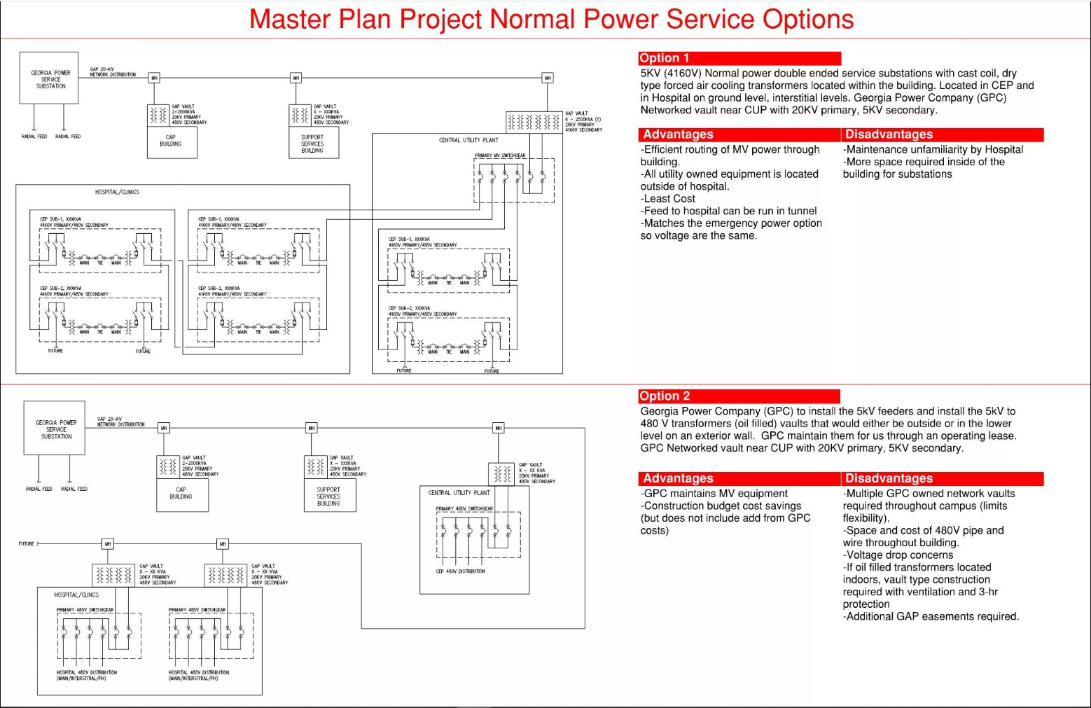
Once the location for the central plant was established, there were two options to consider for how to distribute power to each of the campus buildings. Option one consisted of an incoming utility transformer yard provided by GPC located near the central plan with facility owned medium-voltage distribution to multiple unit substation locations to serve various portions of the buildings. Option two consisted of a GPC provided transformer and incoming utility feed to each building (see Figure 2).
Through a process, the design team and owner selected option one. Therefore, a single GPC utility transformer yard (primary 20 kilovolts, secondary 5 kV) would be located adjacent to the central plant and be the main supply for the entire campus.
Electrical distribution design
Once the service location was determined, the design team focused planning efforts on the location and quantity of interstitial spaces to appropriately serve the hospital departments. There were multiple factors to consider in optimizing the placement and square footage served from each interstitial service location throughout the building.
First, is selecting noncustom equipment sizes for unit substations. Using custom-sized equipment can cause first cost and lead time implications, as well as life cycle maintenance cost and complexity.
Second, the team considered the load demand of each floor. In the main hospital design, the basement was designated for high-power density spaces, such as the central kitchen, laboratory and supply chain. Floors one through four were diagnostic and treatment areas, such as radiology, surgery and the emergency department. Floors five through 19 were designated for various acuity patient room floors and support spaces.
Based on this density distribution, the team conducted a concurrent analysis of how each segment of the building would be served with power and heating, ventilation and air conditioning. Ultimately the team agreed on two interstitial service floors on levels three and 11, which were 75% mechanical, electrical and plumbing spaces, and an additional main normal and emergency electrical room in the basement. Electrically, this allowed the system to feed upward from each level that included the main electrical rooms.
During this process, it’s important to have engaged with the facility maintenance team on the complexity of the electrical system. In the example of this project, the owner was very keen toward resiliency as this will be the largest children’s hospital in the southeast region of the United States. This led the design to include multiple levels of resiliency. Multiple utility feeds were planned to the main medium voltage switchgear in the central plant, as well as providing loop feeds to unit substations and including a digital power monitoring system at all major pieces of equipment. Each project has varying criteria and budget considerations; therefore, it is important to discuss and document expectations and owner standards early in the design process.
Central plant system
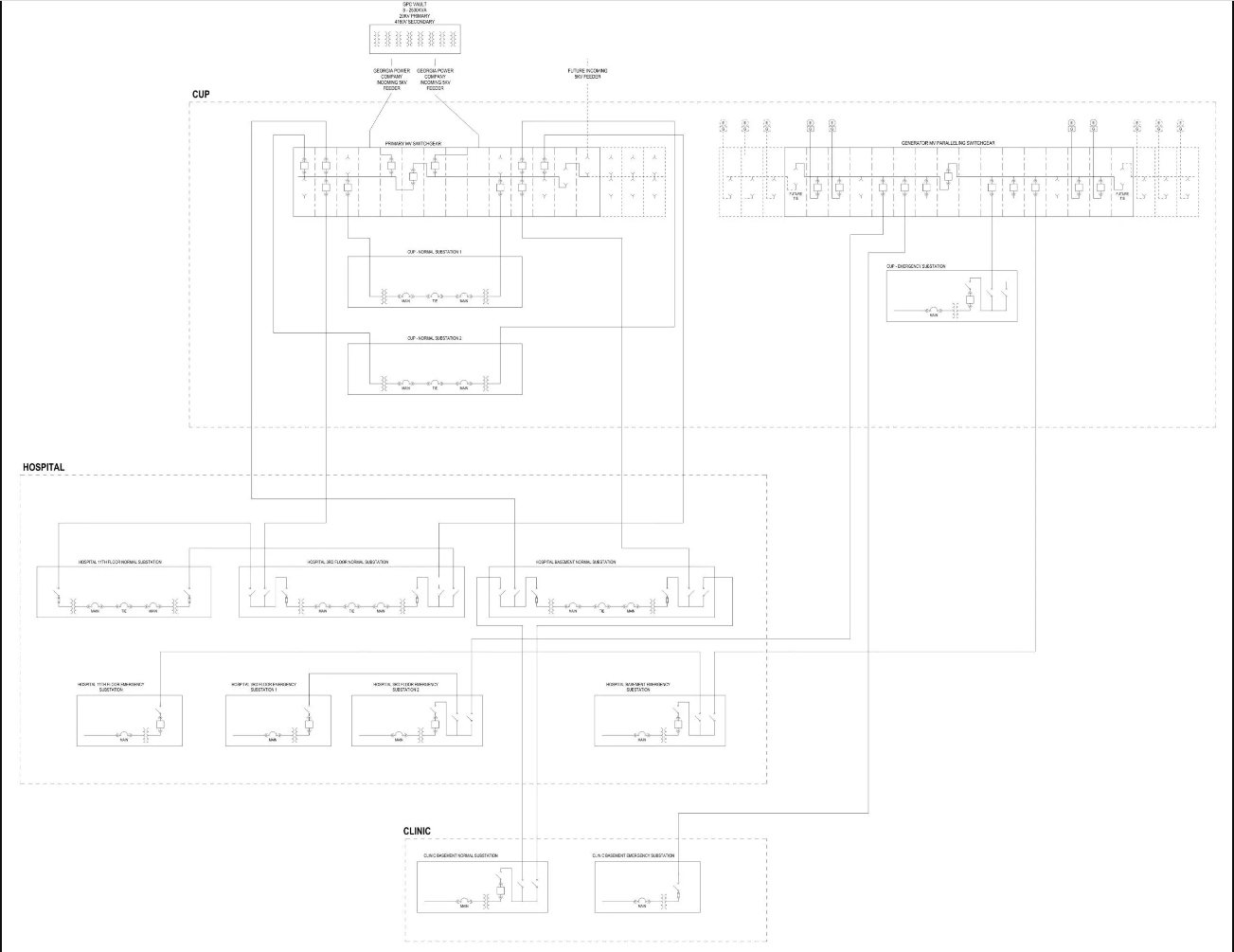
The normal incoming power was coordinated with the local utility provider, and this conversation led to the final decision of providing a networked utility transformer yard adjacent to the central plant on the north side of the site. This transformer yard included eight utility transformers with redundant units if one of the transformers were to fail. From this yard, multiple 5 kV feeds enter the central plant on Level 00 into the customer supplied 5 kV normal system switchgear. This gear then serves 5 kV feeders to the central plant substations, as well as loop feeds to the hospital and clinic building unit substations.
One floor above the normal service entrance were the generators and associated essential system paralleling gear and unit substation. The system was designed for the emergency system to back up approximately 40% of the facility load internally, which equates to approximately 12.7 kVA (or 11.5 kW). Based on this demand load, and the distribution feeder distances, the team decided to provide 5 kV generators.
Medium voltage feeders on the normal and emergency system reduced the quantity and size of conductors routed to the remote unit substations throughout the campus.
While the initial design for the essential standby system is sized for approximately 40% of the campus load, the owner’s criteria directed the design team to plan for expansion of the system to include backing up 100% of the campus at some point in the future. Therefore, the design team planned space to add future generators and associated switchgear in the future.
Another important consideration in the design of large-scale generator plants, especially in urban areas, are the acoustic and pollution control considerations. The team included both an acoustics and wind consultant to assist the team in analyzing the generator plant location and accessories to control sound and pollution. During these conversations, it was decided to locate generators indoors to avoid noise issues and conceal all the equipment at the central plant. In addition, enhanced pollution control and sound attenuation was included in the central plant design.
The generators were located on the second level of the central plant (Level 01) to allow exhausting means directly up through the roof and allowed for an entire wall of mechanical louvers with sound attenuation to have a crossflow across the generators for optimum performance.
Main hospital electrical system
The basement, level three and level 11 where the floors chosen to locate main electrical equipment to serve the associated floors above. The campus schematic one-line shows loop feeds between normal substations and loop feeds between the emergency substations.
On each level the normal electrical rooms were designed with double-ended substations, while the emergency electrical rooms have single-ended substations. While it was an option to provide double-ended substations for the emergency system, it was decided by the design team and owner to not provide this as it wasn’t required to meet the project’s resiliency needs, and therefore the costs outweighed the benefit.
A central uninterruptable power supply system was designed for the hospital to serve critical loads that the owner’s criteria stated could not withstand a momentary loss of power awaiting generator startup. These sensitive systems included all the data rooms, 80% of imaging equipment, all isolation panels for procedure and operating rooms and a receptacle on each intensive care patient room headwalls.
To meet this demand, two 900 kVA UPS systems, each with an N+1 module redundancy, were selected. One UPS served the dedicated data loads, while the other UPS served the patient care and imaging loads.
Given the size of the hospital floorplates, multiple branch electrical rooms were required on each level. The design included placing one electrical room in each smoke compartment. This scheme was chosen for several reasons.
First, as each smoke compartment is a maximum of 22,500 square feet, this matches the typical area that is optimal for branch circuit conductor lengths to meet voltage drop requirements without exceeding #8 AWG conductors.
Second, the team planned to place the fire alarm notification panels in each electrical room, which allows for one notification appliance circuit panel within each smoke compartment. Thus, fire alarm circuits would not need to cross smoke compartment boundaries and could minimize the use of costly two-hour rated fire alarm cable systems required to meet survivability codes.
Clinic building
The clinic building was originally planned to be a 10-story 325,000-square-foot building with planned future floor additions above. However, future moved to current design and the building will now be a 17-story 500,000-square-foot building when completed at the end of this project.
Given the height of this building an interstitial floor was designed for the mechanical system to distribute air throughout the building. Electrically, due to lower load demand from an ambulatory care facility, it was able to be served through a main normal and emergency room in the basement, each with a single-ended substation.
Because the design team was aware of the future growth early in design, future capacity was already incorporated into the electrical system so no other major equipment was necessary to meet the demand of the additional seven floors.
The post "Case study: Electrical system design for hospital campuses" appeared first on Consulting-Specifying Engineer