
How to successfully design for cost-effective air handling redundancy
Learning Objectives
- Become aware of facility types that greatly benefit from maintaining some level of cooling and dehumidification if the air handling unit serving an area is down.
- Understand two equipment arrangements for connecting air handling units and the advantages and disadvantages of each.
- Recognize the nuances and details of how connected air handling units operate in normal versus connected modes.
Air handling insights
- Some building types, such as large corporate data centers, have the budget and mechanical room space to provide total backup or spare air handling units. However, other occupancies such as hospitals, some types of labs and industrial facilities need some amount of spare capacity but usually do not have the budget or building area to accommodate a full “spare” air handling unit.
- A cost-effective solution is to connect air handling units so that, in the event one unit is down for maintenance, some reduced level of both air movement and cooling and dehumidification is still available.
When the operations staff at a facility with critical loads, such as hospitals, research labs or large data centers, gets an alert that air conditioning has stopped in an area, it sets a lot of urgent activity in motion. Technicians rush to the air handling unit (AHU) and begin troubleshooting for the cause. It may be a simple fix or it may involve significant downtime to remedy the situation.
In the meantime, the occupants begin to experience discomfort, heat-sensitive equipment may begin to overheat or room air pressure relationships, critical to a healing environment, may be compromised. In these situations, minimizing downtime is priority one.
If the problem is in an AHU and the unit has multiple supply fans, air movement can continue. However, if the problem is the cooling coil, cooling and dehumidification may be out of service for an extended time. Temporary room spot coolers can help in some situations but not in rooms that require high levels of filtration, for example. The noise, reduced cooling and distraction of temporary units are not acceptable for the time it may take to replace a fan motor or, even worse, replace a coil.
Even if there is no sudden urgency, there are still maintenance tasks that must be done that require the unit to be down, such as cleaning coils and changing filters.
Designing redundant air handling systems
Highly critical facilities that require 2N redundancy, in which there is twice the amount of equipment needed with no single point of failure, may use backup or spare AHUs that can be quickly activated to serve while the problem unit is being serviced. That redundancy comes at a high cost — more mechanical room area, equipment and controls to procure, install and maintain.
Hospitals, large laboratories and some research or industrial facilities can keep going if some reduced level of air conditioning is still available, even if it’s not full cooling. A spare or redundant AHU would accomplish this goal, but the available mechanical space and the project budget often do not accommodate a full spare AHU.
For facilities that need to continue operating but can accept a lower level of service for a limited period of time, is there a more cost-effective solution?
An alternative to full backup AHUs is to connect two AHUs to serve the same areas. Each AHU is sized for some percentage of the total load. The operational intent is that, if one unit goes down for an extended period, the other unit can back-feed the areas served by the down unit to maintain not only air flow but some amount of temperature and humidity controlas well. This alternative omits the need for allotting space in the mechanical room and for the installation and maintenance costs for a spare AHU.

Figure 1: Schematic layout of multiple air handling systems serving different areas. Control dampers (CD) are indicated for connecting the systems and for prioritizing specific areas as required. Courtesy: Smith Seckman Reid Inc.
While connected AHUs do not provide the full backup capacity of 2N redundancy, they do reduce the number of single points of failure:
-
There are two independent air paths.
-
If properly planned with the electrical engineer, the two units can be served by different electrical sources, as far upstream as practical (back to main switchgear if desired). Thus, an electrical outage in the source for one AHU would not result in a total loss of air movement and temperature/humidity control. Further redundancy can be provided by using multiple variable frequency drives (VFDs) on each fan in a fan array. In this arrangement, each fan can be served by a different electrical source path, further removing a single point of total failure. This provides more redundancy than using a VFD for the entire fan array and one standby VFD, in which case one source of electric power can be a single point of failure.
While the idea sounds relatively simple, there are several impacts to the design of the mechanical system. In developing the concept, questions and concerns arise:
-
What special components and additional controls will be needed? How much of the connected operation can be remotely activated and how much must be manual?
-
What are the unintended consequences? Will operation of connected units result in additional operational concerns on the equipment?
There are two ways to connect two AHUs: a cross-connect arrangement and “twinned” units. This engineering team has designed both types of systems and picked up some lessons learned along the way.
Creating cross-connected air handling units
In a cross-connected arrangement, two units are located independently and connected with ductwork. The units could serve different areas or the connecting ductwork could enable both units to serve the same areas. If serving different areas, the units could be sized differently.
In normal operation, each unit operates independently. The supply fans modulate to maintain duct static pressure setpoint, the return fans track the supply fans minus the exhaust/outside air quantity and return dampers modulate to maintain outside air quantity. The control valves for each unit’s coils modulate to maintain the discharge air temperature setpoint for that unit. When in airside economizer, each unit operates independently in damper modulation.
As shown in Figure 1, the cross-connect dampers are normally closed.
If one unit goes down, cross-connect mode is manually activated. The cross-connect dampers open to allow the operating unit to serve areas of the downed unit.
Several operational and control changes are needed for this mode:
-
The supply fans now must look at duct static pressure of both systems to determine fan operating points.
-
Because one unit is now serving two areas, there may be a need to prioritize the areas served for the limited amount of air available. This may require some combination of additional control dampers, closing selected smoke dampers or commanding terminal boxes to close or reduce air flow.
-
A big question to consider is what happens to the exhaust fans in both areas. Do they fully stop? Fans serving hazardous areas, such as isolation rooms, must continue to operate. If those fans are in the area of the “off” unit, how does that impact the air balance at the “on” unit? This may require the building automation system (BAS) to poll the operating exhaust fans and provide a new outside air total for return fan operation, since return air flow is often controlled to match the differential of supply air minus exhaust/outside air.
-
This is further complicated if there is exhaust-to-outside air heat recovery. Additional controls would be needed to isolate the heat recovery component of the down unit.
-
Because the units serve different areas and possibly different smoke compartments, the response of the AHUs to a fire alarm may change. For example, looking at the cross-connect in Figure 1, if AHU 1 is down and AHU 2 is serving areas A as well as C and D and there is a fire alarm in area A, AHU 2 now responds as if there was a fire alarm in the area it normally serves. A detailed description of what happens when a unit is serving an additional smoke area is needed to coordinate the correct action of the fire alarm and the AHU.
While this arrangement is more complex to operate, there are a few advantages:
-
Unit sizes can be different due to different loads served.
-
If there is a need for emergency ventilation requiring 100% fresh air, one unit can go into this mode while the other unit runs in a normal mode of return and outside air.
Best practice suggests using a cross-connect arrangement in a situation where, after the design documents have reached a “point of no return” completeness, the owner requests “some means of backup cooling to certain areas”. There is likely no opportunity to redesign mechanical rooms or even make substantial changes to the AHUs due to being different sizes and serving different areas. Cross-connecting provides the capability to direct a limited amount of air to prioritized areas. A graphical interface on the BAS makes it quick and easy for the facility staff to select which areas to prioritize.
There may also be situations in which an owner needs to add cross-connection capability to existing AHUs. While this is feasible, be aware of the nuances and details noted above that must be anticipated for successful implementation.
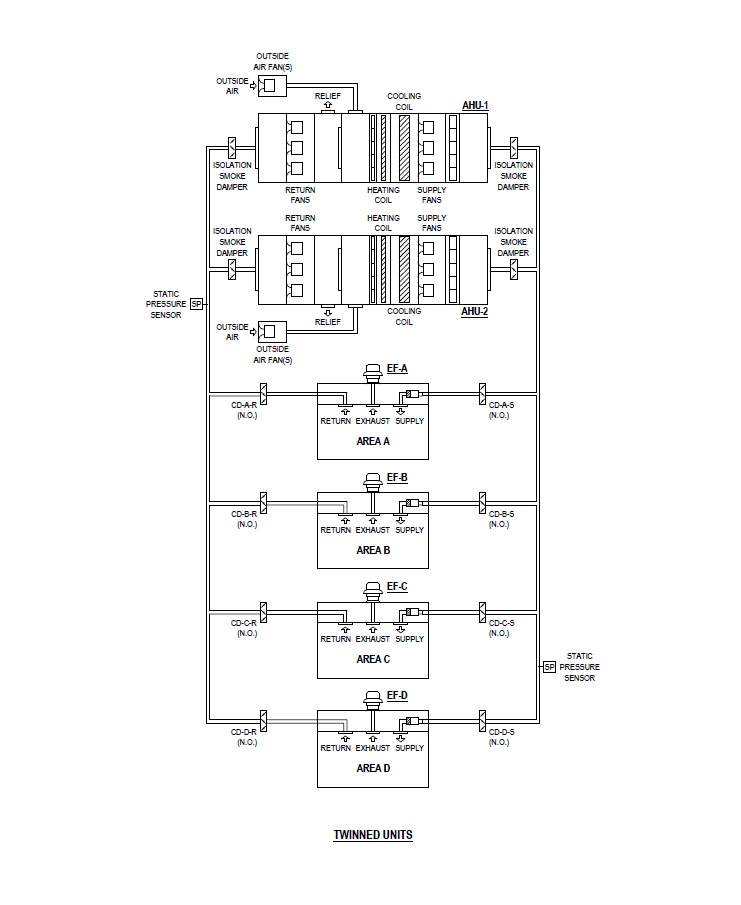
Figure 2: Schematic layout of multiple air handling systems serving the same areas. Control dampers (CD) are indicated for prioritizing specific areas as required. Courtesy: Smith Seckman Reid Inc.
Twinned air handling units
A simpler, more straightforward arrangement is to closely align two units in parallel. The units are equally sized and serve the same areas. The units are close enough to share common return and discharge plenums (see Figure 2).
Generally, the two units “operate as one.” The supply fans in both units modulate to maintain the same duct static pressure setpoint. A different twist of this arrangement is that the return fans modulate to maintain a negative static pressure setpoint in the common return plenum. This was done to accommodate real life conditions; ideally, each return fan would track the supply fans minus the exhaust/outside air differential.
However, the tolerances of air flow measurement at two supply fans results in return fans operating at different setpoints, with the unintended consequence of the two return fans fighting each other to pull enough return air to meet airflow setpoint. By controlling all fans to a common static pressure setpoint in the return plenum, this single setpoint is a simple operating target.
One nuance is that the use of a dedicated outdoor air system (DOAS) or, at minimum, an outside air fan, helps maintain correct airflow when using return plenum pressure to control return fan speed; changes in wind direction or atmospheric pressure don’t have an effect on air flow from the outside air intake to the mixing plenum. Each unit’s cooling coil modulates to maintain the discharge air temperature setpoint for that unit. When in airside economizer each unit operates independently.
When one unit goes down, the twin unit begins to automatically ramp up to its maximum capacity to try and meet the supply duct static pressure setpoint.
As in the cross-connected scenario, there are deeper operational issues to resolve:
-
Because one unit is now serving a larger area, there may be a need to prioritize the areas served. This may require some combination of additional control dampers, closing selected smoke dampers or commanding terminal boxes to close or reduce air flow.
-
As with cross-connected units, a big question to consider is what happens to the exhaust fans in both areas. Do they fully stop? Fans serving hazardous areas, such as isolation rooms, must continue to operate. Maintaining correct air flow presents a challenge. In full unit shutdown of one unit, there will be a loss of control of building pressure due to half the minimum outside air (OA) being cut off from the system essentially. This is alleviated with the use of the airflow measuring station on the minimum OA duct from the DOAS. The BAS can open the operating unit OA damper more to meet the air flow demand of both units if needed. This is the advantage of using a DOAS or outside air fan when using twinned units.
-
Unlike the cross-connected layout, one of two units in a twinned arrangement would not be able to go to 100% outside air in an emergency ventilation scenario — both units would need to operate at 100% fresh air because they share a common return plenum.
How will the owner benefit?
While the original and primary purpose of connected AHUs was to find a cost-effective way to provide some level of cooling in the event of an AHU going out of service, owner feedback has focused on the increased efficiency of maintenance. Routine tasks, such as changing filters, are done more quickly, resulting in less downtime and loss of service. The benefit of less downtime is magnified when considering more extensive maintenance or repair such as cleaning coils or replacing coils or fans.
By having the option of scheduling time-consuming service in mild weather, the maintenance staff can perform tasks on one unit while the other AHU can come closer to fully meeting a reduced load during those mild conditions.
Connecting AHUs to serve multiple areas can provide enough cooling and air movement to maintain some level of acceptable indoor conditions if one unit is down without the additional cost or mechanical room area of a totally spare AHU.
Considering the additional complexity of cross-connected units, a twinned approach offers a simpler operational approach than a cross-connected arrangement to remove a single point of failure in cooling availability.
There is less downtime when maintenance, such as cleaning coils or changing filters, is performed when a unit is down.
If the twinned units or cross-connected units are served by separate electrical power sources, another single point of failure can be removed.
The use of twinned units has been positively received on several projects and one owner is incorporating the use of twinned units in future projects. They consider twinned units a cost-effective means of providing air movement as well as cooling and dehumidification while acknowledging the reduced downtime for maintenance.
Do you have experience and expertise with the topics mentioned in this content? You should consider contributing to our CFE Media editorial team and getting the recognition you and your company deserve. Click here to start this process.
The post "How to successfully design for cost-effective air handling redundancy" appeared first on Consulting-Specifying Engineer