
Learn the pros and cons of centralized and decentralized generator systems
Generator insights
- When designing or assessing campus-style distribution systems, it is important to focus on centralized versus decentralized standby power systems.
- Decentralized standby generators offer electrical and geographic diversity to prevent single points of failure and can be less expensive due to localized and right-sized electrical distribution.
- Centralized standby generators offer shared capacity and N+1 redundancy, but can be more expensive and require larger equipment.
When designing or assessing campus-style distribution systems, the topic of centralized versus decentralized standby power systems is a necessary focus. This article will explain the various attributes associated with a variety of standby generator systems. It is intentionally written in a format that starts by making a case for each arrangement by addressing the positive and beneficial aspects then finishes with the negative compromises and limitations.
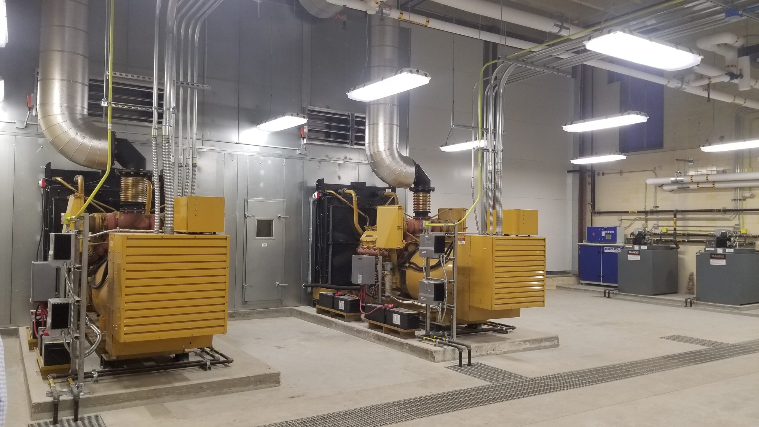
Figure 1: Two 600 kW 4,160 V standby generators were relocated to a remodeled space that was sized for a third generator and larger generators. This system is planned for expansion to operate as a centralized location in a remote utility plant. Courtesy: IMEG Corp.
Decentralized standby generators
It is very common for a campus to grow in a manner that results in multiple distributed standby generator systems spread across the campus both electrically and geographically. The typical arrangement is an essential electrical system (EES) consisting of one or more generator sets, serving a defined “building.” Other buildings, usually separated by age, have a separate EES.
The primary reason for distributed systems is due to the cost and complexity of centralized systems and the lack of capacity in the older generator systems to accommodate new building additions. Many projects lack the budget to overhaul and upgrade the existing EES. The primary benefit of decentralized arrangements, other than initial cost to each building, is both electrical and geographic diversity to prevent single points of failure.
If a natural disaster damages the east side of a building or campus, the utility and standby power systems may be damaged beyond immediate repair. While the portions of the building or campus served will be without power, the other areas of the building may still sustain power, allowing for continued operation. This approach is popular in mission critical and health care campuses where evacuation and shutdowns are not acceptable.
For campuses that experience frequent growth and renovation, the distributed configuration can be less expensive due to localized and right-sized electrical distribution providing a lower cost to feeders and electrical gear. Because the needs of each building on a campus may vary, additional savings may be had for systems that do not need to meet more stringent requirements of Level 1 systems, as defined in NFPA 110: Standard for Emergency and Standby Power Systems.
For example, a health care campus will likely have Level 1 EES to serve the areas that are within the International Building Code (IBC) occupancy classification of I-2 (institutional), and may also have IBC occupancy classifications of B (business), A (assembly), S (storage), etc.
The other occupancy types may be able to have a Level 2 EES as defined by NFPA 110 or may only require emergency loads as defined by NFPA 70: National Electrical Code (NEC) Article 700 and would not fall under Article 517 or NFPA 99: Health Care Facilities Code, which both govern health care designs.
Providing different levels for EES serving different buildings on a campus may also allow for different fuel types and storage amounts. In this example, the Level 1 EES would likely consist of diesel standby generator sets with on-site storage sufficient for 96 hours of operation (with or without refueling during the 96 hours).
A Level 2 EES for a smaller medical office building may be a single natural gas standby generator with a local temporary connection cabinet. Buildings that do not need an EES at all could get by with battery backup of emergency and egress lighting and fire alarm systems.
When consulting with a campus, one simple question to ask the client is if the building can be evacuated at any time, without hesitation. If the answer is yes, then it’s likely the backup power requirements can be less stringent when compared to areas that cannot be evacuated.
There are, however, negative aspects of a distributed or decentralized standby power system and the most glaring one is the lack of shared capacity. For example, if a campus has 4 megawatts (MW) of total standby power through four 1-MW generator sets and if none of those sets can be connected in parallel, the available capacity at any point in the system is limited to 1 MW. This can have the effect of increasing costs for future projects, additions or renovations if the closest and most convenient generator system lacks capacity.
Additionally, if one generator is taken out of operation for maintenance, the other generator sets on campus are not able to back feed, requiring temporary connections. NEC Article 700.3(F) recognizes the vulnerability of a single generator and requires installed, temporary connection capability that can be avoided with paralleled generators of adequate size.
Decentralized generator systems also spread out the equipment causing additional maintenance hassles and increased footprints. Fuel storage is required for each, fuel treatment is required for each, battery systems are multiplied and testing is multiplied. Each generator location needs to be coordinated with outside air intakes for the heating, ventilation and air conditioning (HVAC) system and noise concerns within the campus and adjacent properties.
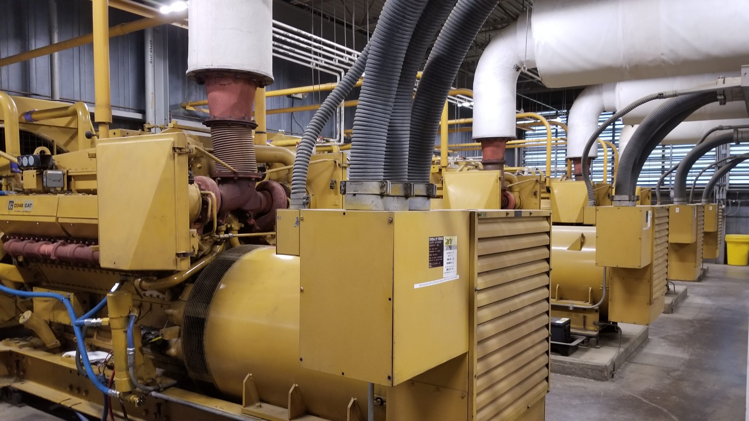
Figure 2: Four 600 kW 480/277 V diesel generators located in a central utility plant serving 4,000 A paralleling gear in an adjacent room. Courtesy: IMEG Corp.
Centralized standby generators
A central utility plant, or CUP, can be located adjacent to the buildings served or can be remote from the buildings served. The CUP can contain chilled water systems, heating water or steam systems and electrical distribution systems for both normal (utility) and standby (emergency) sources.
Centralized electrical distribution can be independent of mechanical systems and locating them inside of a CUP is just one option. It is common for normal utility sources to be centralized, typically at the 15 kilovolt (kV) distribution voltage class. This may or may not be equipment owned by the client, though it is common for the facility to own and operate the medium-voltage distribution for the normal service. Likewise, standby generator sets can be centralized and distributed at the same voltage as the normal service.
Large buildings or campus arrangements are subject to voltage drop concerns when distributed across the space, therefore, one of the first decisions the team should consider is the distribution voltage for both the normal and standby systems. In the U.S., typical building service voltages are 208/120 V for smaller buildings and 480/277 V for larger buildings (with stepdown transformers for 208/120 V loads). The centralized generator system can distribute at the building service voltage or at higher voltages to reduce wire size, which will aid with costing and voltage drop.
Alternatively, centralized systems can take advantage of 5- or 15-kV voltage ranges to greatly reduce the cost to distribute over longer distances, even several miles away. When using medium-voltage distribution, the buildings served will need to plan for large transformers to step-down to the building service voltage. Step-down transformers can be part of single-ended or double-ended unit substations. The type and location is based on budget, space and desired redundancy. Additionally, 15 kV fused switches are provided at the transformer primary and can include radial or loop outputs for future expansion capability.
A centralized and remote location can improve the exterior aesthetics of the various buildings served by removing exterior enclosures from the areas around each building. Freeing up space around buildings allows for more flexibility for future expansions and alleviates concerns with noise and exhaust emissions near buildings.
The ability to parallel standby generator sets together is the strongest argument for centralized generator systems. The size and quantity of standby generator sets required to achieve N+1 sizing can be less than decentralized. Let’s work through an example:
-
Building A has 550 kilowatts (kW) of emergency load.
-
Building B has 375 kW of emergency load.
-
Building C has 900 kW of emergency load.
Total emergency load is 1,825 kW. Assume the generator sizing calculations (for voltage dip and frequency dip) require a generator sized for 2,400 kW, minimum. A centralized system can achieve N+1 with two 2,500-kW or three 1,250-kW standby generators. For a decentralized generator system to achieve N+1, each building would need a pair of generators, bringing the campus total to at least six.
When determining the number of generators to parallel to serve the total campus load, the designer then needs to evaluate several factors, such as type of building, loads served, how they interact with the generator that creates voltage dip and how long they can sustain being without power before the EES is online.
For instance, in a Level 1 system that feeds a health care occupancy, the engineer must determine the loads required to connect within 10 seconds or the sum of the critical and life safety branches. This load is what drives the smallest engine size allowed. Let’s revisit the example, this time with the load broken out by essential branches, as defined by NFPA 99 Article 517.
-
Building A has 20 kW of life safety branch load, 175 kW of critical branch load and 355 kW of equipment branch load.
-
Building B has 10 kW of life safety branch load, 75 kW of critical branch load and 290 kW of equipment branch load.
-
Building C has 35 kW of life safety branch load, 350 kW of critical branch load and 515 kW of equipment branch load.
Now we can see that we have 665 kW of load that needs to be online within 10 seconds and after running generator sizing calculations, we may find that the minimum generator size needed is 900 kW, making 1,000 kW (or 1,250 kW in our example) the preferred choice for each generator. Next, the designer needs to determine the available growth that this minimum size allows. If the campus is expected to double in size over the next 20 years, then the recommended minimum generator size needs to increase accordingly.
The team needs to determine how the centralized generators and associated equipment will be protected. Keeping the paralleling controls and distribution switchgear inside conditioned (and access controlled) buildings is preferred. While generators may be in exterior enclosures and generators can feature onboard paralleling controls to reduce the footprint of the distribution, electronics always prefer a conditioned environment with low dust, humidity and a moderate temperature range.
Remote buildings, such as a CUP that house the generator sets, fuel polishing systems, day tanks, engine controllers and associated electrical distribution should take future expansion into consideration. The layout of the generators, for example, should allow for additional units or accommodate replacement with larger units as the campus grows. This requires a larger footprint or at least the planning for building expansion, which drives up the costs associated with centralized systems.
Centralized systems are not without their challenges. Initial costs can be higher when a greenfield campus is initially constructed because the central system needs to be sized (or scalable) for all projected campus growth. It is also common for centralized systems to be a retrofit solution for an existing campus looking to expand further.
In addition, feeder routes must be carefully coordinated with other utilities and future expansion plans. The routing could be underground duct banks, routing through utility tunnels or a combination thereof, but the pathway should be separated from normal utility pathway to prevent a single excavator or event from damaging both normal utility and emergency services.
Underground duct banks are also subject to ground water ingress and the need for periodic maintenance holes (due to wire spool length limitations) means that designers should consider methods of providing adequate drainage of conduit and maintenance holes. Drainage systems may include connection to stormwater drainage or pumping solutions.
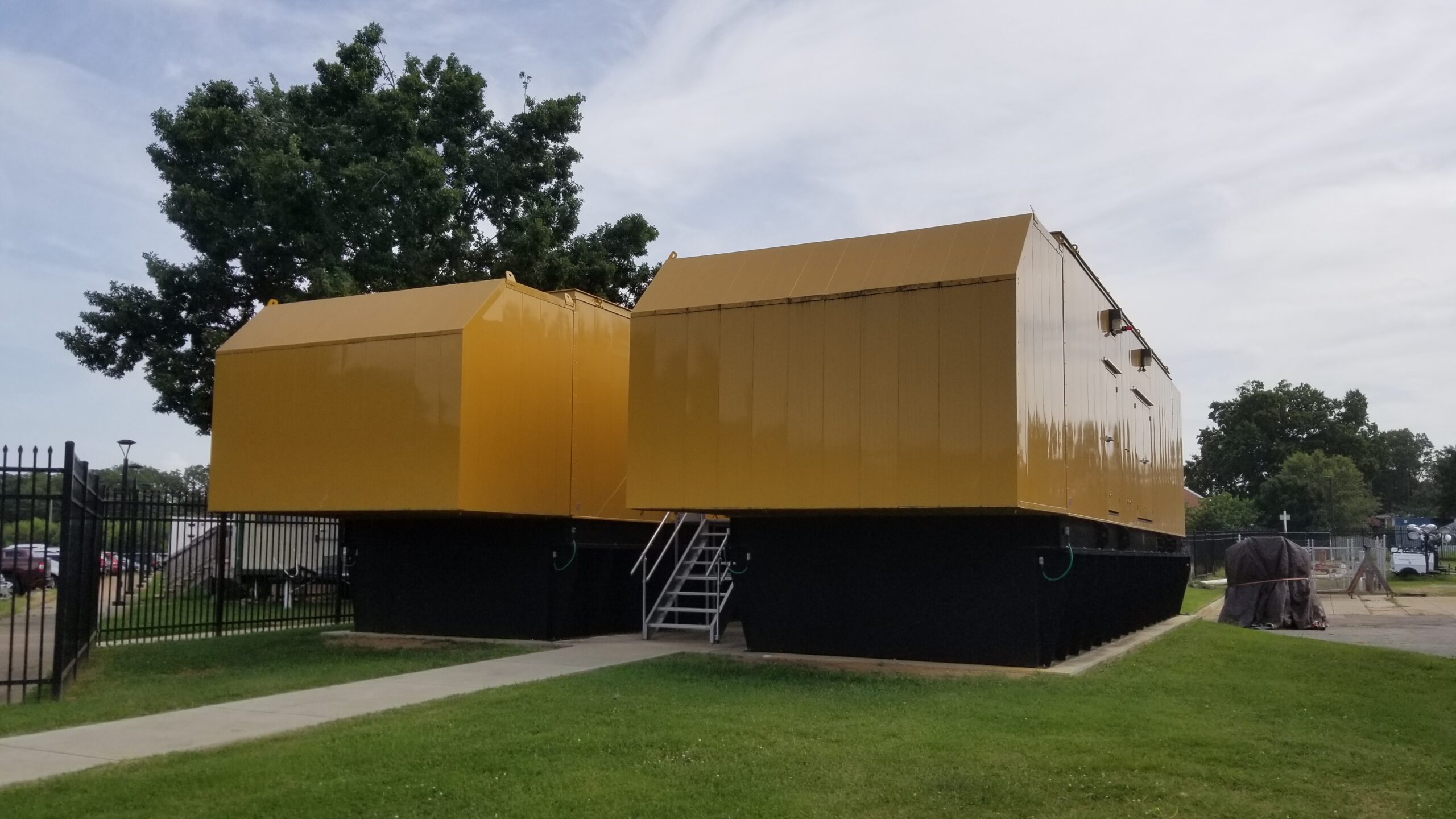
Figure 3: Two 2 MW 13.2 kV diesel generators in outdoor walk-in enclosures provide campus backup of utility feeds serving a central utility plant. The generators serve 15 kV-class metal-clad switchgear with operable breakers for automatic operation with loss of utility. Courtesy: IMEG Corp.
Centralized standby generators for emergency and utility backup
Some campuses want a full backup of the normal utility through standby generators that operate at the service entrance voltage, which is usually 5- or 15-kV class. Solutions that offer this level of backup are often subject to more rigorous requirements, such as U.S. Environmental Protection Agency (EPA) Tier emission levels.
An advantage to having a lower emission EPA Tier standard allows for load curtailment, which can provide financial savings through agreements with the local utility. These generators are typically independent of emergency standby generators; however, we can consider an arrangement in which large, standby generators operating at the utility service voltage can provide both essential standby and utility backup power.
When using campus backup generators for emergency backup, there are several aspects to be aware of when doing this. There are several reasons why it is not acceptable to simply rely on the campus backup generator to provide the essential electrical branch for each building.
-
Division of branches is not possible with utility backup.
-
Two sources of power within a patient care area, where required by NFPA 99, is not possible.
-
Transfer switches are still required in each building, for each required branch.
-
Branch segregation required within NEC Article 700, 701 and 702 (or NEC 517) are still required at the branch circuit level.
-
Each building will need transformers if the generator voltage is different from the building voltage. These transformers are separate from the incoming service transformers. This is commonly accomplished using unit substations when the generator voltage is 5 or 15 kV, but can occur with traditional exterior or interior step-down transformers.
-
The building transfer switches need additional programming to inhibit retransfer to normal when the campus backup is online.
Courtesy: IMEG Corp.
Learning Objectives
- Learn pros and cons for centralized and decentralized generator systems.
- Acquire strategies for centralized campus power backup.
- Review and example on centralized generators for both utility backup and emergency electrical system duties.
The post "Learn the pros and cons of centralized and decentralized generator systems" appeared first on Consulting-Specifying Engineer